Tuning the Marimba Bar and Resonator
Jeff La Favre
jlafavre@gmail.com
Before we discuss the marimba
in particular, it is helpful to review some aspects of the science
of sound. In physics, sound can be described as a wave. We cannot
see the vibrating movement of air molecules, so we do not have a
visual sense of sound. However, wave phenomena in water are familiar
to everyone. If a stone is dropped into a pool of water, waves propagate
away from the stone in a circular pattern. A casual observer might
reason that the wave is caused by horizontal movement of water away
from the stone, but this is not true. Leonardo da Vinci described
it eloquently: "it
often happens that the wave flees the place of its creation, while
the water does not; like the waves made in a field of grain by the
wind, where we see the waves running across the field while the grain
remains in place." In the case
of the water wave, the visual effect is caused by the cyclical rise
and fall of the water level and can be depicted as a sine wave graphically.

The graph is useful in defining some
of the dimensions of the wave. The x axis represents the direction of wave propagation
and the y axis represents the amplitude (height) of the wave. The normal water
level is represented by a value of y = 0. The top of the wave is +ym above
the normal water level and the bottom of the wave is -ym below
the normal water level. The wavelength ( )
is represented by the distance at which the wave pattern begins to repeat itself.
Key positions on the wave are designated with the terms node (place where
the wave crosses the x axis) and antinode (the position of maximum distance
above or below the x axis). )
is represented by the distance at which the wave pattern begins to repeat itself.
Key positions on the wave are designated with the terms node (place where
the wave crosses the x axis) and antinode (the position of maximum distance
above or below the x axis).
A dimension of sound waves
that is of particular interest in music is the frequency. If we graph
the wave with time as the x axis, then it is possible to determine the
frequency (which is related to the musical note). The period T
is defined as the time interval in which the wave motion begins to repeat
itself.

The frequency is calculated
by the following formula:
f = 1/T.
The standard unit for frequency
is Hertz or Hz (cycles per second). The notation that
I have used on these web pages sets middle C as C4. Then the next C
above middle C is C5, etc. The A above middle C (A4) is used as the
standard note for tuning purposes and in the United States a tuning
standard of A4 = 440 Hz is usually used (however, my marimba and many
commercial marimbas are tuned to A4 = 442 Hz to yield a brighter sound
that is supposed to sound better with the orchestra).
The Marimba Bar
The marimba bar vibrates in complex patterns that produce a sound uniquely
characteristic to the instrument. An understanding of the sound quality
(timbre) is gained by study of the vibrations. Each type of vibration
is called a mode of vibration. In a scientific study of a C3 (C below
middle C) marimba bar, Bork et al. (1999) identified 25 modes of vibration
in the range of 0 to 8,000 Hz.
The tuning of a marimba bar may
be elementary (only one mode tuned) or complex (several modes tuned). In
the early 20th century, commercial marimbas were tuned only in the fundamental
mode (the named note of the bar). During the 1920's a higher level of tuning
was initiated by tuning the fundamental mode and the first overtone (the
second transverse mode). This improvement in tuning yielded a more desirable
sound from the bar because the first and second transverse modes were tuned
to a harmonic interval. Later, master marimba builders started to include
a tuning of the third transverse mode, a procedure sometimes called triple
tuning. The finest modern marimbas are triple tuned and may have additional
modes tuned or partially tuned to create an even more harmonious sound from
the bars.
The
tuning level adopted in fabricating a marimba bar will depend on the
goals of the builder. For a simple instrument, all that is needed is
a tuning of the fundamental mode. On the other end of the spectrum, a
concert marimba will at least be triple tuned and further tuning refinements
will yield the best possible sound. An understanding of several modes
of vibration is essential for the builder who aspires to create a high
quality instrument. Careful study of the 12 modes discussed below is
recommended for those who are interested in tuning bars to a high level.
However, you may wish to restrict
your reading only to the first three transverse modes and then skip down
to the Tuning the Marimba Bar section
This section explores
some of the more important modes of vibration in the marimba bar.
The first 12 modes of the C2 bar for the La Favre marimba are presented
below. Several methods were used to discover and measure the frequencies
of vibration and to determine the mode responsible for each frequency.
The marimba bar was struck at various locations on the top surface
as well as the bar edge. The audio resulting from mallet blows was
recorded digitally and the frequencies determined by Fast Fourier
Transformation (FFT). Prominent frequencies found by FFT were confirmed
by strobe tuner. Modes of vibration were identified by a "salt" method
as follows: 1) bar was supported by foam blocks at the nodes of
the fundamental mode, 2) salt was sprinkled on the top surface of
the bar, 3) bar was subjected to sound at the frequencies determined
by the FFT analyses. The sound source was a speaker connected to
a tone generator. When exposed to sound at a frequency that matches
a mode of the bar, the bar will begin to vibrate in that mode. The
bar vibration causes the salt to accumulate at the places on the
bar where vibration is minimal (the nodes). The pattern of salt
on the bar after exposure to a specific frequency of sound is diagnostic
for the mode. Check this page for more information on the salt method.
First Transverse Mode
The first mode (mode 1) of the bar is the mode with the lowest vibration
rate (cycles of vibration per second or Hz). Mode 1 is a transverse
out-of-plane type of vibration or simply, transverse. Since
it is also the lowest vibration rate for a transverse mode, it is named
the first transverse mode. Transverse modes of vibration are
the type where the bar vibrates up and down along its length. As an
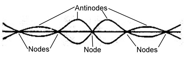
aid in visualizing the vibration, look at the illustrations and photo
below. The first illustration is a diagram of the bar, looking at the
bar edge along its length. The bar is represented by a single line,
with the curved lines representing the extreme positions in the vibration
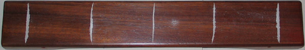
cycle. The photo shows the location of the nodes on the top surface
of the C2 bar where salt accumulated after striking the bar repeatedly
in the center with a mallet. The second illustration is animated with
the same viewpoint as the first illustration. Movement of the bar is
exaggerated in both illustrations. The bar moves up and down to the
greatest degree in the center of its length. This location on the bar
is called the antinode. There are two positions along the length
of the bar where there is no up and down motion and these are called
the nodes. The first transverse mode gives rise to the fundamental
of the bar. The first transverse mode of vibration is always tuned
in a marimba bar, regardless of its location on the keyboard. The La
Favre marimba was tuned to a standard of A4 = 442 Hz and in this standard,
the C2 bar is tuned to 65.70 Hz.
First
Transverse Mode (Fundamental)

(illustration above derived from Bork, 1995 for a C3
bar - nodes do not line up with bar photo below because the illustration
was drawn for a different bar - the exact location of nodes varies with
bar dimensions and other factors)

C2 bar La Favre marimba - salt sprinkled on bar and
struck with mallet in the center of the bar - salt accumulates at the
nodes

Striking the bar in the center
results in maximum excitation of mode 1 vibration because this is the
location of maximum deflection. Conversely, striking the bar at one
of the nodes results in very little excitation of mode 1 because there
is little movement of the bar in this zone for mode 1. Therefore, the
bar can be supported at the nodes with little damping effect on mode
1 vibration (glockenspiel, xylophone, vibe and marimba bars are supported
at the nodes of mode 1).
First Torsional Mode
The next mode (mode 2) of
vibration in the C2 bar was found at 102.2 Hz and identified as
the first torsional mode of vibration. Yoo
et al. (2003) studied the transverse and torsional modes of vibration
in two commercial marimbas. They compared the higher modes of vibration
to the fundamental by calculating a ratio (higher mode Hz / fundamental
mode Hz). For the La Favre C2 bar, the ratio for the first torsional
mode is 1.56. In other words, this mode vibrates at a rate
1.56 times greater than the fundamental. For a Malletech C2 bar,
Yoo et al. (2003) measured the first torsional mode with a ratio
of approximately 1.9 (judging from their graph and information
in the text).
A torsional mode of vibration has a twisting type of motion. If you
were to hold both ends of the bar and twist it along its length, the
bar would move in a pattern of the first torsional mode. In the first
diagram below the torsional motion is depicted with colored arrows.
The red arrows depict the movement of the bar during half the vibration
cycle and the blue arrows depict the movement during the other half.
As the left front corner of the bar moves down (red arrow), the right
front corner moves up. At the same time the left rear corner is moving
up while the right rear corner is moving down. This mode has two nodes,
represented by dashed lines. One node runs down the center of the bar
length and the other perpendicular to the bar length at the center.
There is no movement at the node lines during vibration. The second
illustration below is an animation of the bar vibration, again exaggerated
to help you visualize the movement.
The first torsional mode of vibration is usually not tuned. The first
torsional mode is not excited into vibration to any great degree unless
the bar is struck near a corner, where the antinodes are located. Here
is what Bork et al. (1999) had to say about this mode of vibration in
their C3 bar "This mode radiates weakly, since adjacent regions
of opposite phase cancel the sound radiation at long wavelengths (here
1.06 m)." Therefore, this mode may not cause much of a problem
if left untuned, because the sound waves radiating from adjacent corners
of the bar tend to cancel each other.
CLICK HERE for more about tuning
the first torsional mode (and the lack of a need to tune this mode)
First Torsional Mode


C2 bar La Favre marimba - salt sprinkled on bar and
struck with mallet at corner while partially supporting the bar at the
center to suppress the first transverse mode - salt accumulates along
the node running the length of the bar.

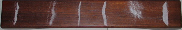
Second Transverse Mode
The next mode (mode 3) of
vibration in the C2 bar is the second transverse mode. The first,
second and third transverse modes are the modes that are usually tuned
in a marimba because they are key components contributing to the timbre
of the bar. The second transverse mode vibrates in a pattern similar
to the first transverse mode, but the second transverse mode has three
nodes compared to two for the first mode. A node at the center of the
bar is an important feature of the second transverse mode. If the bar
is struck exactly in the center at this node, there will be very little
excitation of the mode.
The second transverse mode
of the C2 bar is tuned to 262.8 Hz. Recall that the first transverse
mode of the C2 bar is tuned to 65.70 Hz. Dividing 262.8 Hz by 65.70
Hz, we obtain a value of 4.00. The calculation indicates that the tuned
second transverse mode vibrates at a frequency 4 times greater than
the first transverse mode, or two octaves above the fundamental.
Second Transverse
Mode

(illustration above derived from Bork, 1995 for a C3
bar - nodes do not line up exactly with bar photo below because the
illustration was drawn for a different bar - the exact location of nodes
varies with bar dimensions and other factors)

C2 bar La Favre marimba exposed to sound from tone generator
at 262.8 Hz - salt sprinkled on bar accumulates at the nodes - look
carefully in the center of the bar where a small amount of salt has
accumulated, marking the central node.

Second Torsional Mode
The next mode (mode 4)
of vibration in the C2 bar was found at 595 Hz and identified as
the second torsional mode of vibration.
The ratio compared to the fundamental is 9.06. For a Malletech
C2 bar, Yoo et al. (2003) measured the second torsional mode with a
ratio of approximately 8.5 (judging from their graph).
Unlike the first torsional mode, this mode has antinodes at the center
of the bar, located at each bar edge ( red and blue arrows located at
the center of the bar in the first diagram below). This mode of vibration
can be excited during normal playing if the mallet hits the bar more
toward the edge in the center of the length. Here is what Bork et al.
(1999) had to say about this mode in their C3 bar "This mode radiates
better than the lower (1-1)-mode because its wavelength of sound is
shorter. When the bar is hit vertically on the top, close to the edges,
the (2,1) mode .... has almost equal amplitude as the (4.0) mode in
the radiated spectrum." For clarification here, (1-1) = first torsional
mode, (2,1) = second torsional mode, (4.0) = third transverse mode.
Therefore, the second torsional mode may be more problematic in tuning
due to its strong radiation of sound.
CLICK
HERE for more information on the second torsional mode.
Second Torsional Mode


C2 bar La Favre marimba exposed to sound from tone generator
at 595 Hz - salt sprinkled on bar clears from antinodes and accumulates
in center

Third Transverse Mode
The next mode (mode 5) of
vibration in the C2 bar is the third transverse mode. It was
tuned to 662.2 Hz. This type of vibration is similar to the first and
second transverse modes, but in this case there is four nodes. Importantly,
an antinode occurs at the center of the bar. In contrast to the second
transverse mode, this mode is excited when the bar is struck in the
center, just as the first transverse mode. This mode is usually tuned
as well, but only in the lower range of the keyboard. The third transverse
mode is usually tuned to three octaves and a major third above the fundamental
(i.e., a frequency of 10.08 times greater than the frequency of the
first transverse mode).
Third Transverse
Mode

(illustration above derived from Bork, 1995 for a C3
bar - nodes do not line up with bar photo below because the illustration
was drawn for a different bar - the exact location of nodes varies with
bar dimensions and other factors)

C2 bar La Favre marimba exposed to sound from tone generator
at 662.2 Hz - salt sprinkled on bar accumulates at the nodes

First Lateral Mode
The next mode (mode 6) of
vibration in the C2 bar was found at 786 Hz and identified it as the
first lateral mode of vibration (also known as the first transverse
in-plane mode). The ratio compared to the fundamental is
12.0. The lateral modes of vibration are transverse in type,
but the movement is not up and down. The vibratory movement is left
and right (from the player's perspective). In order to excite this mode
of vibration to any great degree, it would seem that the bar must be
struck on its edge, at the center of the length. However, the first
lateral mode is known to contain a vertical element, at least in some
bars. Therefore, a normal vertical strike on the bar can activate this
mode, as was found for the La Favre C2 bar. Professional tuners are
known to apply tuning methods such as "wedging" to this mode
when it causes a conflict with a tuned transverse mode (Weiss, 2003).
Bork et al. (1999) note that "A weak vertical component
can be observed, probably due to the slightly asymmetrical scoop"
in the C3 bar they studied. In other words, the bar they investigated
did not have a perfectly symmetrical undercut arch, which they believe
gives rise to some up and down movement in the bar for the lateral mode.
Even when striking the bar with a normal vertical stroke then, the first
lateral mode might be excited to some degree.
The first illustration below
indicates the direction of vibration with red and blue arrows. The two
nodes are marked with black circles. The nodes of the lateral modes
are unique in that they run vertically through the bar (i.e. in the
z direction). All other modes listed on this page have nodes that run
horizontally (i.e., in the x and y directions).
CLICK
HERE for more information on the first lateral mode.
First Lateral
Mode


C2 bar La Favre marimba exposed to sound from tone generator
at 786 Hz - salt sprinkled on bar is pushed off edges in the center

Third Torsional
Mode
The next mode
(mode 7) of vibration in the C2 bar was found at 1203 Hz and identified
as the third torsional mode of vibration. The
ratio compared to the fundamental is 18.3.
For a Malletech C2 bar, Yoo et al. (2003) measured the third
torsional mode with a ratio of approximately 16.5 (judging from
their graph).
Third Torsional
Mode


C2 bar La Favre marimba exposed to sound from tone generator
at 1203 Hz - salt sprinkled on bar clears from antinodes and accumulates
in center
Fourth Transverse Mode
Mode 8 was measured at 1287
Hz and found to be the fourth transverse mode. The ratio compared
to the fundamental is 19.6. This mode is similar to the third
transverse mode, except that it has five nodes instead of four. Also
note that this mode has a node at the center of the bar, like the second
transverse mode. Therefore, this mode will not be excited to any great
degree when striking the bar in the center. I believe that some professional
tuners also tune this mode in the lower bass bars and probably to a
ratio of 20 times the fundamental frequency.
Fourth Transverse
Mode
(illustration above derived from Bork, 1995 for a C3
bar - nodes do not line up with bar photo below because the illustration
was drawn for a different bar - the exact location of nodes varies with
bar dimensions and other factors)
C2 bar La Favre marimba exposed to sound from tone generator
at 1287 Hz - salt sprinkled on bar accumulates at the nodes
Fourth Torsional
Mode
The next mode
(mode 9) of vibration in the C2 bar was found at 1585 Hz and was
identified as the fourth torsional mode of vibration. The
ratio compared to the fundamental is 24.1. For a Malletech
C2 bar, Yoo et al. (2003) measured the fourth torsional mode with
a ratio of approximately 25 (judging from their graph). The
fourth torsional mode is unique compared to all other torsional
modes presented here. It has two node lines running the length of
the bar instead of one.
Fourth Torsional
Mode


C2 bar La Favre marimba exposed to sound from tone generator
at 1585 Hz - salt sprinkled on bar accumulates at the nodes
Second Lateral Mode
The next mode (mode 10) of
vibration in the C2 bar was found at 1680 Hz and was assigned to the
second lateral mode of vibration.
The ratio compared to the fundamental is 25.6. Both the first
and second lateral modes commonly include some vertical vibration in
addition to the lateral element. That is the reason why they are activated
to a certain degree when the mallet strikes specific locations on the
top surface of the bar. Bork et al. (1999) found a significant vertical
element of vibration in the second lateral mode of their C3 bar. I do
not have the sophisticated instrumentation required to evaluate simultaneous
vibrations in the horizontal and vertical planes. The salt method I
employed is not clearly diagnostic for this mode in my hands. Therefore,
the illustration I provide below includes the vertical element as detailed
by Bork et al. (1999). The nodes of the lateral element are represented
by black circles. The nodes of the vertical element are represented
by dashed lines and are similar to the third torsional mode.
The salt pattern obtained
on the bar after exposure to 1680 Hz is more difficult to understand
than any other mode studied for the C2 bar. This is most likely due
to the presence of significant vertical and lateral elements of vibration
for this mode. Without a more detained evaluation of the interaction
of vertical and lateral elements, obtained with sophisticated scientific
instruments, I am not in a position to explain the salt pattern observed.
Second Lateral
Mode


C2 bar La Favre marimba exposed to sound from tone generator
at 1680 Hz - salt sprinkled on bar accumulates along the bar edges in
the center.
Fifth Torsional
Mode
The next mode
(mode 11) of vibration in the C2 bar was found at 1957 Hz and identified
as the fifth torsional mode of vibration. The
ratio compared to the fundamental is 29.8. For a Malletech
C2 bar, Yoo et al. (2003) measured the fifth torsional mode with
a ratio of approximately 34 (judging from their graph).
This mode is similar to the third torsional mode, except it has
four node lines across the bar width instead of three.
Fifth Torsional
Mode


C2 bar La Favre marimba exposed to sound from tone generator
at 1957 Hz - salt sprinkled on bar clears from antinodes and accumulates
at center node and at nodes across the bar width
Fifth Transverse
Mode
Mode 12 was
measured at 2097 Hz and found to be the fifth transverse mode.
The ratio compared to the fundamental is 31.9. This mode is similar
to the fourth transverse mode, except that it has six nodes instead
of five. Also note that this mode has a antinode at the center of the
bar, like the third transverse mode. Therefore, this mode will be excited
when striking the bar in the center. As far as I know, this mode is
not tuned in any commercially available marimbas.
Fifth Transverse
Mode
C2 bar La Favre marimba exposed to sound from tone generator
at 2097 Hz - salt sprinkled on bar accumulates at the nodes
The graphs below plot the
relative rates of vibration (ratios) for modes of the La Favre marimba.
An analysis of this type is useful for the marimba builder who wishes
to refine the tuning of the bars. The untuned torsional and lateral
modes can interfere with the harmonious sounds of the tuned transverse
modes if the ratios have similar values. For example, in the La Favre
marimba the first lateral mode has ratio values very close to the third
transverse mode in the bottom two octaves. Therefore, the first lateral
mode may degrade the tuning of the third transverse mode. Further investigation
is needed in order to evaluate the level of degradation. If the lateral
mode vibrates at an intensity much less than the third transverse mode,
then there is no problem. The relative intensity for both modes must
be measured for several locations that are reasonable spots that a player
would hit during a performance. The graphs are a starting point for
investigating problem torsional and lateral modes. My investigation
in this area is ongoing. You can see some of my latest findings on my
page covering torsional and lateral
modes.


Marimba bars may vary in
the order of certain modes depending on a number of factors, particularly
the shape of the undercut arch and general bar dimensions (length, width,
thickness). The ratio values for the torsional modes found for the La
Favre C2 bar are similar to those found by Yoo et al. (2003) for a Malletech
C2 bar. In addition, the order of the first four transverse and first
four torsional modes are the same for the La Favre C2 bar and the Malletech
C2 bar (bottom two octaves). Yoo et al. (2003) did not study the lateral
modes in their bars, which prevents a comparison for the lateral modes.
The mode order for a C3 bar studied by Bork et al. (1999) was not the
same as the La Favre bar. Bork et al. (1999) found the following order
of modes: first transverse, first torsional, second transverse, first
lateral, third transverse, second torsional, second lateral, fourth
transverse, third torsional, fifth transverse, fourth torsional. Nevertheless,
the modes discussed above are those that the tuner should be aware of
if bars are to be tuned to a high standard. The tuner needs to be aware
that the order of modes in their bar may be different than the order
for the La Favre C2 bar.
It should be noted here
that the bar vibrates in more than one mode at a time and in
fact usually vibrates in several modes when struck. The modes
active in vibration and their relative strength depend on where
the bar is struck and the kind of mallet used. For bass bars, soft
mallets that have a relatively high mass will excite the lower modes
of vibration more than hard mallets of lower mass. Thus, soft heavy
mallets are commonly used at the bass end of the instrument while
hard mallets are used at the treble end. Furthermore, the lower
modes of vibration will be active for longer periods of time after
the bar is struck than the higher modes. This can be easily heard
in a bass bar struck with a medium mallet. The higher modes (second
and third transverse) are easily heard immediately after the bar
is struck, but in a fraction of a second they die out and the fundamental
alone is obvious. Bork (1995) states the following:
"When the frequencies of the partials of a bar behave like 1:4:10,
the second partial decays four times as quickly, the third partial
ten times as quickly as the fundamental." In other words, in
a bar tuned like a marimba bar (1:4:10), the fundamental rings four
times as long as the second transverse mode and 10 times longer than
the third transverse mode.
Tuning the Marimba Bar
I provide this information
primarily for those who are interested in building their own marimba
and those who want to understand how a bar is tuned. If you are thinking
about retuning an existing marimba, please be advised that it is easy
to permanently ruin the tuning of a bar, which then must be replaced.
If you want to retune an out of tune marimba, I would suggest that you
fabricate several practice bars first. If the possibility of ruining
a bar is not an acceptable outcome, it would be best to send the bars
to a professional tuner. In any case, you must be willing to spend a
considerable amount of time learning the tuning process. It is not something
that can be done quickly.
I have tried to provide
enough information to enable you to tune a bar to a relatively high
degree. The more modes you attempt to tune, the more difficult the
tuning will be. If you want to build a marimba for serious music,
then I would suggest you consider tuning at least the fundamental
and second transverse mode. For more complete tuning, tune the third
transverse mode and perhaps even the fourth transverse mode. To
achieve the highest standard, you may need to partially tune some
problem torsional or lateral modes. I did not tune any torsional,
lateral or fourth transverse modes on my marimba at the time of
bar fabrication. Currently (January, 2007), I am examining the torsional
and lateral modes in my bars and have started some retuning work
( second torsional
and first lateral modes information
on first torsional mode)
In order to achieve an accurate
tuning, you probably need to use a strobe tuner (a real strobe, not
an instrument that attempts to mimic a strobe). Unfortunately, strobe
tuners are expensive. If you don't have access to a strobe tuner, you
might try using a less expensive electronic tuner (the type with a needle
and scale and/or LEDs that indicate "in tune") but you may
find it difficult, if not impossible, to tune overtones with these tuners.
Before the development of strobe tuners in 1942, professional tuners
employed sets of tuned bars as standards, using their ears for tone
comparisons. Even today professional tuners rely on aural technique
for certain aspects of tuning. However, tone matching requires a keen
ear. If you are gifted with sensitivity in tone perception, then you
may be able to use your ear for tuning. Since I don't have this skill,
I need to rely on a strobe tuner.
The
information in the previous section can be used to formulate a tuning
strategy for the marimba bars. The transverse modes of the marimba bars
are harmonically tuned (that is, the transverse mode overtones are whole
multiples of the fundamental frequency). The first transverse mode
of the marimba bar is tuned to the fundamental, the second transverse
mode is tuned to the fourth harmonic (two octaves above the fundamental)
and the third transverse mode is tuned to the tenth harmonic (three
octaves and a major third above the fundamental).
I triple tuned the bass register
on my marimba, C2 to G#3 (first, second and third transverse modes tuned
to fundamental, 4th harmonic and 10th harmonic respectively), which
imparts a more consonant complex tone. Bars in the middle register (A3
to C5) were double tuned (first and second transverse modes tuned to
fundamental and 4th harmonic respectively). Overtones of the higher
register (C#5 to C7) reside above the range of the instrument and are
sustained for very brief time periods or may even be inaudible. For
these reasons, I did not tune the overtones in the higher register.
Tuning of overtones becomes
more difficult in the higher registers due to the very brief sustain.
The third transverse mode has the shortest sustain time and becomes
difficult to tune above G#3. Higher up, the second transverse mode also
becomes very difficult to tune. With my strobe tuner, I found it difficult
to get a fix on the frequencies for overtones above the limits stated
above. A more skilled tuner might push the tuning to higher points on
the keyboard. Nevertheless, there comes a point in the keyboard where
the bars no longer vibrate in a specific overtone, which limits the
tuning of an overtone mode to bars below that point.
A simple rectangular bar
does not vibrate with harmonic overtones. In order to tune the bar to
harmonic overtones, it is necessary to cut an arch from the bottom.
The removal of wood changes two properties of the bar important in the
tuning process: 1) flexural strength and 2) mass. Removing
wood from the bar results in a reduction in flexural strength
and a reduction in mass. However, flexural strength is proportional
to the cube of the bar thickness and mass is only proportional to the
thickness (Bork, 1995). A reduction in flexural strength results in
a lower vibration rate while a reduction in mass results in an increase
in vibration rate. These are opposite effects that occur when wood is
removed from the bar. However, since the flexural strength is related
to the cube of the bar thickness, this property is more influential
than mass in areas of the bar where flexing occurs. For example, when
wood is removed from the center of the bar, the vibration rate is reduced.
Why? Because the flexural strength is reduced more than the mass. Since
the bar flexes to a great degree in its central region, the reduction
in flexural strength dominates over the loss of mass. In contrast, at
the very ends of the bar there is no flexing in the transverse modes.
Therefore, a drop in flexural strength at the bar ends does not effect
a reduction in the rate of vibration. When wood is removed from the
ends of the bar, the mass is the only important property for tuning.
Since a reduction in mass results in an increase in the rate of vibration,
removal of wood at the bar ends will raise the rate of vibration. A
good understanding of the effects of wood removal at various locations
on the bar is the key to tuning.
For a person who is learning
the process, begin triple tuning by cutting a very conservative arch,
which results in a bar several semitones above the target note. Then
small amounts are removed from specific areas of the arch to achieve
the harmonic intervals (the fourth and tenth harmonics, i.e. 4 and 10
times the fundamental frequency).
The fundamental is lowered
more than the overtones when material is removed from the center of
the arch (area 1 in illustration below). The second transverse mode
is lowered most when material is removed somewhere between the center
and end of the arch (area 2). The third transverse mode is lowered most
when material is removed near the end of the arch (area 3). When
all three frequencies are at the desired harmonic intervals, then material
is removed evenly across the arch to approach the target note.

This tuning method should
seem logical if you recall the modes of vibration for the bar. The first
transverse mode of vibration (the fundamental) requires maximum flexing
of the bar in the center (its antinode). By removing material in the
center, the bar becomes more flexible (less stiff), which results in
a slower rate of vibration. The antinodes for the second transverse
mode of vibration (tuned to the fourth harmonic) are on both sides of
the bar center, so removal of material there results in a more flexible
bar in the locations where this mode requires maximum flexing. The third
transverse mode of vibration (tuned to the tenth harmonic) has antinodes
at the bar center and near each of the zones labeled 3 in the illustration
above. Therefore, removing material from the areas labeled 3 results
in more flexibility for two of the three antinodes of this mode.
For more information on the locations where wood should be removed
to tune the transverse modes, CLICK HERE.
Cutting the arch
The amount of wood removed
from the bottom of the bar varies, with more removed toward the bass
end of the instrument (see photo of bars farther below). I selected
the C4 bar as a starting point. An arch was penciled in along the bar
edge, centered along the length, starting 1/4 of the length from each
end and running along the center of the bar thickness in the middle
of the bar length. For the first few bars I used a band saw to cut the
rough arch. Unfortunately, I don't have a very good band saw, which
made it difficult to cut a proper arch. So I developed a method using
the table saw, which I will describe later. Once the rough arch is cut,
the strobe tuner is used to determine the frequencies of the fundamental
and other transverse modes. The modes tuned depends on the bar, for
C4 only the first and second transverse modes were tuned - see below
for measurement procedure. You must proceed carefully to tune the modes
to the required harmonic interval(s). For double tuned bars, first tune
the second transverse mode to two octaves above the fundamental, by
removing more wood nearer the ends of the arch. When the proper two
octave interval is obtained, then remove wood evenly across the arch
to drop both fundamental and second transverse mode. For bass bars,
the third transverse mode may have a frequency greater than ten times
the fundamental. If so, then remove material near both ends of the arch
(area 3), and be careful to remove equal amounts on both ends (my table
saw method insures this). You may also need to extend the length of
the arch as well. The key is to remove small amounts of wood and make
frequency measurements after each removal. After the third transverse
mode equals a frequency of ten times the fundamental (three octaves
plus a major third), work on bringing the second transverse mode to
an interval of two octaves above the fundamental. Then remove material
evenly along the arch to drop the fundamental and other modes to the
required frequencies. As you do this, you will probably need to make
minor adjustments by removing more material from specific zones to maintain
the proper harmonic spacing of the fundamental and other modes.
Continue the rough tuning until
you are about 50 cents above the target note (then
the holes are drilled for the cord and finish is applied to the
bar and, then the final tuning is done). You must have patience. I spent
up to 4 hours per bar doing the rough tuning on the first bass bars. As
you do more tuning the process speeds up. In the end I could triple tune
bass bars in 1.5 to 2 hours. I should note here that my work was done
in the winter and my belt sander was in the garage while the tuner was
in the house. Traveling back and forth consumed a lot of time. A professional
can do the tuning in a matter of minutes and they usually have the tuner
near the belt sander. Nevertheless, when you are learning, the process
takes considerably longer. You might try using some scrap wood like pine
to try tuning a bar or two before doing the actual bars for the instrument.
This is advice I have read elsewhere, but I was too anxious to start the
real tuning and skipped this step. I was lucky in that I only ruined one
bar by tuning it too low (I had to reject a few other bars as well since
they did not sound good after tuning). Again, the key is to work very
slowly, especially on the first few bars you tune. After you get a feel
for the tuning, you can become more bold and remove more material with
each tuning cycle.
After I had rough tuned the
C4 bar, I used it as a reference for the arch shape. I worked my way
to the top of the instrument, using the tuned bar as reference for the
next higher note. Then I worked my way down the bass region, starting
with B3. I simply transferred the shape of the arch from a rough tuned
bar to the adjacent uncut bar. But when I made the first cut, I did
not cut all the way down to the line, I left about 1/16 to 1/8 inch
extra wood. Remember, if you cut off too much, you will have to discard
the bar and start over.
I used a table saw and belt
sander (6 x 48 inches) to remove wood from the underside of the bar.
After drawing the arch on the bar edge, I used the table saw to cut
the rough arch. The process is slow, but insures a very accurate arch
symmetrically (I know this method is not used in a production shop,
where a band saw is usually used, but then they have better band saws
than the one I own). Measure the length of the bar and divide by two.
Set the table saw fence to this number. Now raise the saw blade to a
height that is 1/16 to 1/8 inch less than the full depth needed to reach
the arch line in the bar center. Position the bar against the miter
gauge and butt the end of the bar against the table saw fence. Then
run the bar through the blade to make a cut. Then retract the fence
the thickness of the saw blade and make another cut (you will need to
make two cuts for each fence setting, one with each end of the bar against
the fence). Continue making cuts, and drop the height of the blade as
you go to maintain the cuts 1/6 to 1/8 inch below the penciled arch
line. Yes, this is a very slow way to cut an arch, but you can't beat
it for symmetric accuracy and for uniform depth of cut across the width
of the bar. After you cut the arch on the table saw, smooth the arch
with the belt sander. Then take measurements with the strobe tuner.
If a great deal of wood remains to be removed from the arch in specific
areas, then use the table saw. Use the belt sander for removing smaller
amounts. I alternated between using the table saw and sander as I worked
the arch down. You don't want to use the belt sander to an excessive
degree because this hand method can yield a non-symmetrical arch. You
need to be very careful with the belt sander as it removes wood quickly.
Sand just a small amount and then make measurements with the strobe
tuner. After a while you will have a better feel for the amount of sanding
required to drop the frequency a certain amount.
After you have drilled the
holes and applied the finish to the bars, you are ready for the final
tuning. Bars vibrate at different frequencies at different temperatures.
Therefore, it is best to do the final tuning in a temperature controlled
environment. If you don't have a temperature controlled environment,
restrict your final tuning to parts of the day when the temperature
is similar. In my case I did the final tuning at a time of year when
my house was being heated. For final tuning the temperature was always
between 71 and 75 degrees F and the very final tuning of each bar was
done at 73 degrees F. Keep in mind that when you sand the arch, the
bar will heat up. So you must wait for the bar to return to room temperature
before you make a determination of the final tuning. You should do the
final tuning at a temperature similar to that which you anticipate for
a typical performance with the instrument.
Fixing the tuning of
a bar that is below the desired note
If by accident you tune a
bar slightly below the target frequency, you can raise the frequency
to a limited extent by removing wood from the ends of the bar. Usually
this is done by reducing the thickness of the bar between the nodes
and the bar ends. Removing wood close to the bar end has the greatest
effect. Therefore, you can try chamfering the end of the bar at the
bottom to raise the tuning.

Some Helpful Information
from the Literature
Bork et al. (1999) used modeling
to determine just how sensitive the bar is to removal of wood in the
arch area. They calculated that a removal of only 0.5 mm from the thickness
of the bar in the arch area would drop the frequency of the fundamental
by about 8% (more than one semitone)! You need to think about this for
a minute. A layer of wood 0.5 mm thick is not much at all, yet a removal
of this small amount of wood drops the fundamental more than a semitone.
This is why I state that you need to work very slowly when you are learning
how to tune a bar. You need to appreciate how much the tuning changes
with a small amount of wood removal.
Tuning Problem Lateral
and Torsional Modes
Lateral and torsional modes
can be tuned by cutting notches on the underside of the bar, at
the bar edge in the center of the length (MacCallum, 1969). The
arch in the center region of the bar can also be shaped so that
the bar thickness is greater in the center than the edge (drawing
below), sometimes called wedging or having a wedge cross section
(Weiss, 2003). Properly placed grooves in the arch area can also
help in tuning a problem lateral or torsional mode (Weiss, 2003).
Keep in mind that the wedging technique will also affect the tuning
of the transverse modes. If you are trying to wedge a bar in a retuning
process, you may need to raise the tuning of the transverse modes
first by removing wood from the ends of the bar (as described earlier
on this page). Experienced marimba builders may know which bars in
the keyboard need to be wedged in their design and incorporate the
wedge where needed during the initial shaping of the arch. This is
a much better approach than trying to fix the problem after the transverse
modes are tuned.
I have started to
investigate lateral and torsional modes and how to tune them.
Here is what I have so far.
CLICK
HERE for more about tuning the first torsional mode (and the lack
of a need to tune this mode)
Using the Strobe Tuner to
Measure Frequencies of the Modes
The frequencies are measured
with a strobe tuner. The different modes are emphasized depending on
where the bar is grasped and where it is struck with the mallet. A mode
is brought forth by holding the bar at a position that coincides with
a node (a location where the bar does not vibrate in that specific mode).
A mode is damped if the bar is held at a position that coincides with
its antinode (the location of maximum vibration for the mode).
The Fundamental (First Transverse Mode)
To bring
forth the fundamental, the bar is held at the node of the first transverse
mode and struck at the center of the bar.


The Second Transverse Mode
To bring forth the second
transverse mode, the bar is grasped at its center and struck as illustrated
below. Trial and error with the mallet will allow you to locate the
position where the second transverse mode will sound loudest when struck.
Slightly adjust the position where you grasp the bar until the bar rings
clearly when struck. The fourth transverse mode can be measured as well
with this technique because it also has a node at the center of the
bar.


The Third Transverse Mode
To bring forth the third
transverse mode, the bar is grasped near one end and struck in its center.
Note that the outer nodes for the third transverse mode are closer to
the end of the bar than the nodes for the first transverse mode. Therefore,
holding the bar near the end does not damp the third transverse mode
very much but does damp the fundamental significantly. The second transverse
mode is not excited when the bar is struck in the center because it
has a node there. These are the reasons why the third transverse mode
is excited with this method and the other two transverse modes are subdued
. Some trial and error
may be needed to find the proper place to grasp the bar.


In addition to a little trial
and error in discovering the exact place to grasp a bar and strike it,
you may need to try using different mallets to strongly excite the various
modes.
Drilling the Holes for the
Bar - Finding the Nodes of the Fundamental Mode
After you have rough tuned
the bar to 50 cents above the target note, it is time to drill the holes
for the cord. Place two blocks of foam under the approximate location
of the nodes as illustrated below.

Sprinkle some salt on the
bar in the area of the nodes as illustrated below and then tap very
lightly with a mallet at the center of the bar.

Keep tapping until the salt
accumulates over each node as illustrated below. Mark the node lines
lightly with a pencil on the top surface of the bar. In the photo below
you will note that the salt has not accumulated perpendicular to the
bar length, but at an angle. In a set of bars, some will have nodes
that are perpendicular to the bar length and some may be angled. This
is due to the non-uniform nature of wood.

Mark the center of each node
line with a cross tick (at the center of the bar width - see illustration
below). Before you drill the holes, you should layout all of the bars
with the proper spacing between each bar, as they will be on the instrument.
The hole in the bar that is located near the center of the instrument
width (inboard) is drilled perpendicular to the bar length. The hole
near the end at the outside edge (outboard) of the keyboard must be
drilled at an angle because the adjacent bars are not the same length.
First line up all the node lines for the bars on the outboard side with
a straight edge as illustrated below (i.e., move the bars inboard or
outboard so that all outboard nodes are in a straight line). Then lay
the straight edge over the node lines on the inboard side. Try to align
the straight edge to minimize the distances from the true nodes to the
straight edge. It may not be possible to pass a straight line through
all of these nodes, in which case you must compromise a little. The
object is to align each bar to minimize the distance between where the
holes must be drilled and the true nodes. Move individual bars slightly
toward the center or outside of the instrument to minimize the difference
between the locations where the bar must be drilled and the true nodes.
Then draw two lines across the bars with a straight edge as illustrated
below. These lines mark the locations where the bars must be drilled.
Measure the angle of the outboard line and use the angle measurement
when drilling the holes on the outboard side.
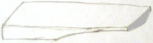
 |
Layout of bars for
marking hole locations
Red lines represent
the true nodes for each bar determined by the salt method described
above. The top of the illustration represents the inboard side
of the keyboard. The inboard line drawn to mark the locations
for the inboard holes is a compromise that comes as close as possible
to each true node while maintaining a straight line perpendicular
to the bar lengths.
|
Look
at this page for the jig I used to drill the holes.
Tuning Analysis of Two Commercial Marimbas
Yoo et al.(2003) examined
the first four transverse modes of vibration and the first five torsional
modes of vibration in a Malletech and a Yamaha five-octave instrument.
For the Malletech instrument, the second transverse mode was tuned to
the fourth harmonic for bars ranging from C2 to D5, after which the
ratio (second / first transverse mode) slowly decreased to a minimum
of about 2.5, and the third transverse mode was tuned to the tenth harmonic
for bars ranging from C2 to C4, after which the ratio decreased to less
than 5 in the highest bars. For the Yamaha instrument, the second transverse
mode was tuned to the fourth harmonic for bars ranging from C2 to F5,
after which the ratio slowly decreased to a minimum of about 2.6, and
the third transverse mode was tuned to the tenth harmonic for bars ranging
from C2 to C#4, after which the ratio decreased to less than 7 in the
highest bars.
Yoo
et al.(2003) found that the first torsional mode frequency ranged
from about 1.9 times the fundamental frequency (lowest notes) to about
1.2 times the fundamental frequency (highest notes). Furthermore, the
second torsional mode ranged between 9.4 times the fundamental frequency
(F3 bar) to 3.9 times the fundamental frequency (C7 bar). The authors
have this to say about the importance of torsional modes: "The
large bars on these marimbas are quite wide, and thus the torsional
bars (I believe they mean torsional modes here) can radiate an appreciable
amount of sound. In normal playing, the bars are struck near their centers,
where the torsional modes have nodes, and thus they will not be excited
to any great extent. On the other hand, if the bars are struck away
from the center, deliberately or not, the torsional modes could contribute
to the timbre.
Bork and Meyer (1985) investigated
the tuning of the third transverse mode. In the study, they compared
tunings of the following six intervals above the third octave: major
second, major second +50 cents, minor third, minor third +50 cents,
major third, and major third +50 cents. Thirty individuals with training
in music were used to judge a preference for the different tunings.
In the composite listening results a preference was identified for a
minor third + 50 cents (i.e. a ratio of 9.88 to the fundamental frequency).
The second most preferred tuning was a major third +50 cents (ratio
of 10.38), which yields a brighter timbre according to the authors.
In summary, Bork and Meyer (1985) state that the tuning of the first
and second transverse modes is critical for pitch perception and that
the second transverse mode needs to be within plus or minus 15 cents
of the double octave for proper pitch perception. Furthermore, "The
third partial (third transverse mode) can influence the pitch slightly,
but this partial mainly contributes to the timbre or tone quality."
Apparently the manufacturers of the Malletech and Yamaha instruments
prefer a brighter tuning for the third transverse mode. For the Malletech,
the tuning was about a major third plus 17 cents and the Yamaha was
about a major third plus 34 cents (frequency ratios of 10.18 and 10.28,
respectively). But we should be cautious about drawing too much from
the analysis of just one instrument from each builder. In fact, some
builders offer voicing options for marimbas, which may include different
tunings of the third transverse mode depending on the desire for a darker
or brighter sound.
Wave forms of complex tones (containing more than one frequency)
As discussed earlier, the
vibrating bar vibrates in more than one mode at a time. As an example,
let us examine the C3 bar, which when tuned at a standard of A4 = 440
Hz, has a fundamental at 130.81 Hz, a fourth harmonic at 523.25 Hz and
a tenth harmonic at 1318.5 Hz. First, listen to each of these frequencies
in isolation (click the links below to hear each frequency - these tones
were generated with computer software):
130.81 Hz
523.25 Hz
1318.5 Hz
Now listen to the combination
of all three frequencies (simulated C3 marimba bar):
130.81+523.25+1318.5 Hz
Below you will find the wave
forms of each of the three frequencies (these are copies of the wave
forms from the computer software used to generate the tones). In generating
these tones, I have attempted to mimic the type of wave forms that the
marimba makes, but keep in mind that this is synthetically produced
sound. The length of the wave form (the x axis) is a representation
of the duration of the sound. The height of the wave form (amplitude)
is an indication of the strength (energy) of the sound (not necessarily
the loudness since the human ear has a variable sensitivity to different
frequencies). The fundamental wave form has the longest duration (I
made the duration equal to 0.7 second). The fourth harmonic has a duration
of 0.35 second and the tenth harmonic is 0.1 second (these durations
may not match exactly those found in a real marimba bar). The vertical
line at the left of the wave form represents time 0, when the bar is
struck. Notice that the fundamental builds more slowly in strength than
the overtones. This is due to the lower frequency and the lag time required
to build resonance in the tube. You should also note that the fundamental
has the highest amplitude, followed by the fourth harmonic and the tenth
harmonic has the lowest amplitude.
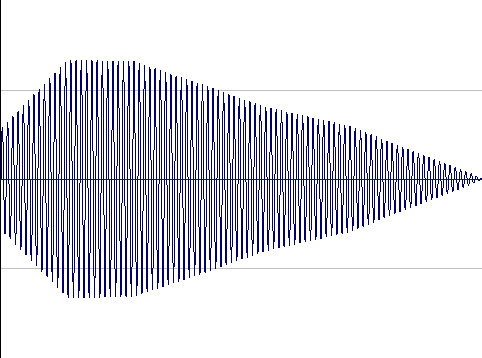 130.81
Hz, the Fundamental 130.81
Hz, the Fundamental
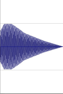 523.25
Hz, the Fourth Harmonic 523.25
Hz, the Fourth Harmonic
 1318.5
Hz, the Tenth Harmonic 1318.5
Hz, the Tenth Harmonic
Below you will find wave
forms for 130 Hz and 1300 Hz. Note that there is one wavelength for
the 130 Hz wave form and ten wavelengths for the 1300 Hz wave form.
These are the wave forms for each tone in isolation. If we mix the wave
forms together to synthesize a complex tone of the fundamental (130
Hz) and one overtone at the tenth harmonic (1300 Hz), then we obtain
a wave form like the second illustration below. The more frequencies
we add together, the more complex the wave form becomes. In this case
I have kept the example simple so that it is easier to make out the
two frequencies in the combined wave form.
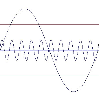 separate
wave forms for 130 Hz and 1300 Hz separate
wave forms for 130 Hz and 1300 Hz
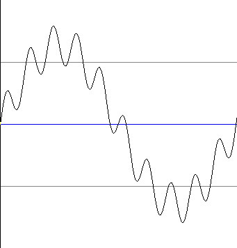 wave
form for a tone with fundamental and the tenth harmonic wave
form for a tone with fundamental and the tenth harmonic
The wave form immediately
above depicts a complex tone. If we were able to visualize the air molecule
movement represented by the wave form, we would notice a pattern of
strong pressure waves passing a point of reference with a frequency
of 130 per second. But each of those strong pressure waves would not
be smooth. Rather, they would have ripples of lower pressure variation
with a frequency of 1300 per second.
In order for a complex tone
to sound harmonious, the higher frequencies (overtones) must be whole
number multiples of the fundamental frequency. Below you can listen
to a complex tone with two harmonic overtones plus another complex tone
that contains overtones that are not harmonic. Listen to both and decide
which one sounds better. Hopefully you will agree that the first link
sounds better. This is the reason why the marimba bars are tuned with
harmonic overtones.
130.81+523.25+1318.5 fundamental
with two harmonic overtones
130.81+587.33+1479.9 fundamental
with two overtones that are not harmonic
Effect of Position of Mallet Blow on Bar Timbre
PLEASE
BE ADVISED: the page linked below contains 40 graphic images
for a total of 2.34 MB, which can take as long as 15 minutes to download
over a phone modem.
Analyses
of sound spectra from bars struck at different positions
Some details about tuning and musical scales
Modern western music employs
an equal tempered scale, which is a compromise developed to facilitate
music played in different keys. An older system, known as Just Intonation,
employs a scale whereby each step up the scale is a whole number ratio
as follows: C 1/1, D 9/8, E 5/4, F 4/3, G 3/2, A 5/3, B 15/8, C 2/1.
Just Intonation results in a collection of notes that are very consonant
due to the whole number ratios employed. However, if one attempts to
shift keys while playing music on an instrument tuned in this manner,
the results are not acceptable.
Some musical instruments,
marimba included, have fixed tunings. In order to play in different
keys with Just Intonation, these instruments must be retuned (or in
the case of a marimba, a different set of bars must be used!). To solve
this problem, the equal temperament scale was developed. In the chromatic
scale of 12 semitones, each step is the 12th root of 2, which preserves
the doubling of frequency with each octave. The 12th root of 2 is 1.059463.
Therefore, you can calculate the frequencies of notes in the scale by
starting at a given point and simply multiplying by 1.059463 to obtain
the frequency of the next semitone. For example, suppose we are tuning
to a standard of A4 = 440 Hz. Then to calculate the frequency of A#4,
calculate as follows: 1.059463 x 440 Hz = 466.16 Hz. To calculate B4,
multiply 1.059463 x 466.16 Hz = 493.88 Hz, etc. If you continue calculations
in this way, you will find that A5 calculates to 880 Hz (i.e., the frequency
doubles on the octave). Below you will find a table that compares the
frequencies of an octave in Just Intonation and Equal Temperament.
| Note |
Just Intonation (Hz) |
Equal Temperament (Hz) |
| C |
264 |
261.63 |
| D |
297 |
293.66 |
| E |
330 |
329.63 |
| F |
352 |
349.23 |
| G |
396 |
391.99 |
| A |
440 |
440.00 |
| B |
495 |
493.88 |
| C |
528 |
523.25 |
The reason I have added this
section is to clarify a detail on tuning the tenth harmonic of the bar.
In the case of the fourth harmonic, the frequency should be exactly
four times the fundamental frequency since the interval is two octaves.
However, the tenth harmonic is not an interval of octaves, and with
equal temperament tuning, the frequency of the tenth harmonic will not
be exactly 10 times the fundamental (with Just Intonation, the tuning
would be exactly 10 times the fundamental). To clarify further, a table
of tunings in equal temperament for the bottom octave of the marimba
is provided.
| Fundamental |
Fourth Harmonic |
Tenth Harmonic |
| C2 (65.70 Hz) |
C4 (262.81 Hz) |
E5 (662.25 Hz) |
| C#2 |
C#4 |
F5 |
| D2 |
D4 |
F#5 |
| D#2 |
D#4 |
G5 |
| E2 |
E4 |
G#5 |
| F2 |
F4 |
A5 |
| F#2 |
F#4 |
A#5 |
| G2 |
G4 |
B5 |
| G#2 |
G#4 |
C6 |
| A2 (110.5 Hz) |
A4 (442 Hz) |
C#6 (1113.77 Hz) |
| A#2 |
A#4 |
D6 |
| B2 |
B4 |
D#6 |
Unfortunately, we are not
finished yet with the details. Apparently, human hearing is a bit quirky.
We tend to hear high notes a bit flat. To compensate for this, an instrument
with a wide compass can be tuned with the high notes slightly sharp.
For my marimba, I employed the following adjustments (stretch tuning):
starting with C#6, one cent was added to the tuning for each semitone
(i.e., C#6 + 1 cent, D6 + 2 cents, etc.). A cent is 1/100th of the interval
between semitones (i.e., there are 1200 cents to an octave).
Human Hearing at Different Frequencies and the Graduation of Bar Width
You will note that my bars
are graduated in width, growing wider with lower notes. One of the challenges
in designing an instrument which sounds in the bass region is to provide
tones that can be easily heard. The human ear has a remarkable range
of sensitivity to sound at different frequencies. Sensitivity in the
bass region is much less than in the range around 1000 to 4000 Hz. In
order to partially overcome this problem, the bass bars are designed
with wider width so that they generate sound at a higher energy level.
 
The graph below depicts the
threshold of human hearing at different frequencies. Note that the human
ear is most sensitive to frequencies in the range of 1000 to 4000 Hz.
The energy level of the sound is graphed in decibels (dB), which is
logarithmic. An increase of 10 dB represents a 10 fold increase in sound
energy and an increase of 20 dB represents a 100 fold increase in sound
energy. Sound at a frequency of 62.5 Hz (lowest note on the marimba)
must be about 30 dB greater than sound at the reference of 1000 Hz in
order for the human ear to detect it. That is, sound at 62.5 Hz must
have an energy level 1000 times greater than a sound at 1000 Hz at the
threshold of human hearing!
Threshold of average human
hearing at different frequencies

Actually the situation is
not quite as bad as it might appear by looking just at the threshold
of hearing (0 dB at 1000 Hz). As the sound level increases, there is
less difference between frequencies in perceived volume, as the graph
below indicates. For example, a tone at 1000 Hz and 40 dB would have
volume approximately equal to a tone at 60 Hz at about 60 dB. In other
words, the 60 Hz tone would need to have 100 times more energy than
the 1000 Hz tone to be perceived at equal volume. In another example,
a tone at 1000 Hz and 80 dB would have volume approximately equal to
a tone at 60 Hz at about 90 dB. In other words, the 60 Hz tone would
need to have 10 times more energy than the 1000 Hz tone to be perceived
at equal volume. I am not sure what the sound levels of the marimba
are in a typical performance, but I don't think the range of 40 - 80
dB is unreasonable (click
here for chart of sound levels). Therefore, the C2 marimba bar must
produce 10 to 100 times more energy than a bar near 1000 Hz to be perceived
at equal volume. I think it is clear that the bass bars I have designed
do not meet this level of energy production. Indeed, most bass instruments
do not produce such sound levels and this is the reason that we commonly
perceive them to have lower volume.
Equal loudness curves
for average human hearing

The audio link below demonstrates
the variable loudness of tones at the same decibel level. Each tone
is 0.5 second in duration starting with C2 (65.41 Hz), followed by C3,
C4, C5 and then C6 (1046.5 Hz).
C2
then C3 then C4 then C5 then C6
Marimba vs. Xylophone and History of Tuning
In the late 19th Century John Calhoun Deagan started manufacturing
xylophones in the United States (Trommer, H., 1996). His enterprise
flourished in Chicago as the J. C. Deagan company. J. C. Deagan Inc.
manufactured a number of different musical instruments including musical
bells, orchestral bells, xylophones, marimbas, vibes and chimes. Another
prominent company manufacturing bar percussion instruments in the United
States during the early 20th Century was Leedy Manufacturing Company.
During the mid 1920's, both of these companies developed methods for
tuning the second transverse mode of bars (Winterhoff, 1927 and Schluter,
1931). Prior to that time only the fundamental was tuned.
The practice of tuning the third transverse mode developed later but
I have not been able to find a reference to the individual or individuals
who developed tuning of this mode. However, it was established prior
to 1969 because it is mentioned by MacCallum (1969) and Moore (1970).
MacCallum states that:
"In the case of marimba bars modern tuning brings down
the errant first two overtones to notes of the same lettered name of
the fundamental note. Tuning the third overtone is often done, but is
difficult and is a luxury."
In his appendix, MacCallum makes it clear that the first overtone
(second transverse mode) is tuned two octaves above the fundamental
and the second overtone (third transverse mode) is tuned three octaves
above the fundamental. He does not indicate the tuning interval to be
used for the third overtone (fourth transverse mode?). As far as I know,
the modern standard used by marimba manufacturers for the third transverse
mode is the tenth harmonic, not the eighth that MacCallum lists. However,
Nakano and Ohmuro (1997) propose a tuning like that suggested by MacCallum
in their patent (the patent is assigned to Yamaha Corporation). Moore
(1970) states the following:
"For particularly accurate tuning, the third partial
as well as the second partial may be tuned to a desirable harmonic relationship
with the fundamental. Tuning of the third partial requires extreme care
and skill on the part of the tuner and is done only upon special request
from the customer. Tuning of the third partial is done only in the low
register of the instruments, on bars with fundamentals of C4 downward.
For marimba and vibe bars the desirable ratios of the second and third
partials to the fundamental are 4:1 and 10:1. For the xylophone bars
the desirable ratios of the second and third partials to the fundamental
are 3:1 and 6:1."
I find it curious that two books published only a year apart (MacCallum,
1969 and Moore, 1970) have such differing views on tuning of the third
transverse mode. The difference is probably due to the two sources the
authors rely on for authority. MacCallum cites a Mr. Del Roper of Monrovia,
California as his source for tuning details. Moore's source for tuning
authority appears to be the Musser Division of Ludwig Industries. Clearly
Musser would be an authority on tuning of that period since they were
a major manufacturer of marimbas. MacCallum states that Del Roper "...is
an expert marimba builder and a virtuoso on the instrument." However,
I don't know if Mr. Roper was associated with a large manufacturer of
marimbas. I suspect that Mr. Roper may have built custom marimbas but
not on a large commercial scale. In that case, Moore (1970) should serve
as the authority for a typical commercial marimba of the period.
The marimba and xylophone
are both fabricated with wood bars, yet the instruments are quite different
in character. The differences are due in part to the tuning of the harmonics.
The transverse modes of the marimba are tuned as even-numbered harmonics
while the xylophone second transverse mode is tuned as an odd-numbered
harmonic (odd-numbered harmonic is the standard in the USA while in
Europe the even-numbered harmonic is preferred for xylophones). Furthermore,
xylophone bars tend to be somewhat thicker than marimba bars of the
same note and are played with harder mallets. In addition, many xylophones
have a compass of C4 to C8, while marimbas commonly have a range that
starts below C4 and usually a top end at C7. The character of each instrument
is further developed via the resonators. A xylophone can be characterized
as an instrument with a bright timbre while the marimba has a dark timbre,
particularly in the bass region.
Each bar of the marimba is
positioned just above a resonator, which amplifies the sound of the
fundamental. The resonator tubes are closed at the bottom end. A closed-tube
resonator amplifies only the odd-numbered harmonics. Therefore, the
4th and 10th harmonics of the marimba are not amplified. This arrangement
results in an instrument with a mellow or dark character. In contrast,
the xylophone has a bright character partly because the second transverse
mode is also amplified by the resonator (if tuned by the USA standard).
This occurs because the second transverse mode of the xylophone is tuned
to an odd-numbered harmonic. The term quint tuning is often used
for this kind of tuning for the xylophone, where the second transverse
mode is tuned to one octave and a fifth above the fundamental (ratio
of 3:1). Quint tuning was developed in the United States by Henry Schluter,
who was the master tuner for the J.C. Deagan company (Schluter, 1931).
The illustration below shows the shape for a xylophone bar according
to Schluter's patent.

In the illustration above, you can see that the bar is
relatively thick in the center and there are two arches in the undercut
rather than one. This shape is one method of achieving the 3:1 ratio
for the second transverse mode and the fundamental. The 3:1 ratio can
also be achieved with one undercut arch of a specific profile (Orduña-Bustamante,
1991). Thinking about the illustration above, and using the information
provided on this page about marimba bars, one can understand the rationale
behind the shape shown above. The deeper arch cuts on each side of the
bar center are near the antinodes for the second transverse mode. Therefore,
the second transverse mode is dropped relatively more in frequency compared
to the fundamental, while the fundamental is maintained relatively high
due to the great thickness of the bar at its center point.
The Marimba Resonator
Here we continue the discussion
of the science of sound. The water wave is a transverse type
of wave because the displacement of the water is perpendicular to
the direction of travel. The sound wave is a longitudinal type
of wave because the displacement of air is parallel to the direction
of travel. The air molecules vibrate back and forth in the direction
the wave is traveling, creating zones of compressed and expanded
air, as depicted in the illustration below.

The animation below depicts
sound waves, with the black dots representing air molecules:

Sound waves can be graphically
depicted by two methods: 1) variation in air pressure or 2) variation
in air displacement. Both methods are compared in the illustration
below:

Note above that the waves
in the two graphs do not line up (i.e. the peaks and valleys of one
are not at the same place as the peaks and valleys of the other).
A node of displacement (where wave crosses the x axis) is
the same location as an antinode of pressure. The zone between
an area of compressed air and a zone of expanded air (the pressure
antinodes) is the zone of maximum air displacement (a displacement
antinode). The zone of maximum displacement is the zone where air
molecules are moving to the maximum degree. The distinction between
displacement and pressure waves is particularly important when illustrating
resonance phenomena for the marimba.
The marimba resonator is
a tube, open at the end next to the vibrating bar and closed at the
other end. A sound wave travels down the tube and is reflected back
at the closed end. As a result, sound waves are traveling in two
directly opposite directions in the tube. If the tube has the proper
length (approximately 1/4 wavelength or odd multiples of 1/4 wavelength),
a standing wave will develop. A standing wave is formed by the combination
of the sound waves traveling in opposite directions. The combined
wave form results in a wave that appears stationary, thus the name standing.
The illustration below can be examined to aid in understanding the
nature of a standing wave.

The yellow wave represents
the wave traveling into the tube and the red wave represents the
wave traveling out of the tube. When the waves combine, the standing
wave depicted in green results. At time 0 the incoming and outgoing
waves are in phase. At time 1/4 T (time for 1/4 of wave to travel
past a point), the incoming and outgoing waves are completely out
of phase and when added together, the wave pattern is a flat line.
As we proceed through one cycle, we see a pattern where the waves
move up and down, but in place. Interestingly, there is no movement
at all at the nodes. The animation below depicts the standing wave
pattern over time.

The animation below depicts
a 1/4 standing wave in the resonator tube. The black dots represent
air molecules. Notice that over the period of the cycle, the number
of air molecules changes at the closed end but does not at the open
end. The closed end is a pressure antinode while the open end is
a pressure node.

Resonance (an amplification
of sound) occurs because part of the sound energy is reflected back
into the tube as it exits. In the vicinity of the open end of the
tube, the impedance drops. The change in impedance is the cause of
wave reflection back into the tube. The reflected wave undergoes
a phase change of 180 degrees, which is required for maintenance
of the standing wave condition. The sound energy that is reflected
back into the tube adds to the energy entering the tube from the
vibrating bar to increase the volume of the sound. Hermann Helmholtz
described the reflection for a tube with two open ends in his book On
the Sensations of Tone : "On our exciting a wave
of condensation at one end, it runs forward to the other end, is
there reflected as a wave of rarefaction, runs back to the first
end, is here again reflected with another alteration of phase, as
a wave of condensation, and then repeats the same path in the same
way a second time."
The closed end of the resonator
tube represents a pressure antinode and the open end a pressure node.
If you think about it, this should be logical. The closed end is
furthest removed from the outside atmosphere, and is the place where
the pressure fluctuates the most. The open end is very close to the
outside atmosphere, and thus can't support wide fluctuations in air
pressure. Conversely, the closed end of the tube represents a node
of air displacement while the open end represents an antinode of
air displacement. This is also logical: the air is allowed to move
more freely at the open end than at the closed end.
For someone unfamiliar
with the subject, confusion may arise when a wave form is drawn inside
the resonator tube. The conventional diagram places a node at the
closed end. It is assumed that the reader understands that the wave
form depicted is a displacement wave form, not a pressure wave form.
A pressure wave form has the antinode at the closed end, where the
maximum fluctuation in air pressure occurs. The illustration below
shows the standing wave form for a 1/4 wave with the displacement
node at the closed end.

The tones produced by musical
instruments are actually a mixture of sound frequencies, usually
in a harmonic series. The mixture gives rise to the timbre (tone
quality) of the instrument. The lowest frequency sound wave of the
tone is called the fundamental or first harmonic. The
overtones (sound waves with higher frequencies) are called harmonics
if they are whole number multiples of the fundamental. For example,
suppose a tone is analyzed and found to contain the following frequencies:
440 Hz, 880 Hz, 1320 Hz and 1760 Hz. The 440 Hz frequency is the
fundamental and establishes the tone as the note A4 (the A above
middle C). The 880 Hz overtone is the second harmonic (i.e.,
twice the fundamental frequency). And 1320 Hz is the third harmonic and
1760 Hz the fourth harmonic.
An interesting property
of a closed resonator tube tuned to the fundamental (a quarter wave
tube) is that only odd-numbered harmonics resonate. The reason for
this is that a displacement node must be located at the closed end
and an antinode must be located at the open end. These conditions
can't be met by even-numbered harmonics. For example, lets take a
1/2 wave, which is twice the frequency of the 1/4 wave illustrated
in the tube above. The half wave could be drawn with a displacement
antinode at the open end but then the node is located in the middle
of the tube, not at the closed end.

So let us try to place the
node at the closed end.

But now there is also a
node at the open end, which won't work. Therefore, even-numbered
harmonics cannot resonate in a closed tube.
What is the next wave pattern
that will resonate in a closed tube? We can fit a 3/4 wave pattern
in the tube with the node and antinode in the correct position.

Recall that the 1/4 wave
form represents the resonance condition for the fundamental. Then
the 3/4 wave form represents the resonance condition for the third
harmonic (3 x 1/4 = 3/4), which is the first available resonance
for an overtone.
So, how do you calculate
the tube length for the resonator? The formula is given below. This
formula is actually the formula to calculate the length of 1/4 of
a sound wave at a given frequency. Since the velocity of sound varies
with air temperature, the wavelength at a given frequency will vary
with the air temperature. Many marimbas have stoppers in the tube
that are not adjustable (at least not easily). Resonators of this
design can only resonate properly at one air temperature since the
wavelength varies with temperature. This becomes particularly critical
for bass resonators, where the changes in wavelength are large. That
is the reason why some high-end marimbas have adjustable resonator
stops on the bass end. Some also have adjustable stops on all resonators,
which allows for fine tuning.
L = v/f/4
Where:
L = length of column (from
opening to closed end) in feet
v = Speed
of sound (1129 ft per second @ 70° F, 1132 ft per second @ 72° F,
1146 ft per second @ 85° F.)
f = frequency of desired
pitch in Hertz
4 = Quarter-wavelength factor
There is also an end
correction factor that should be applied to the calculation.
As it turns out, the wave is not reflected back into the tube at
its opening, but slightly past the opening. There may be other
factors that add to the end correction as well, such as the presence
of the bar. Therefore, it is necessary to subtract an end correction
from the length of the tube. The theoretical end correction for
a resonator closed at one end is 0.61 r, where r is the inside
radius of the tube. But keep in mind that this theoretical end
correction is for a resonator without an obstruction near its open
end. In the case of the marimba (and other similar instruments)
the builder will likely find that the real end correction is greater
than 0.61 r. Also see the section below for more about end correction.
Keep in mind that the calculated tube length is from the surface
of the stopper, so you will need to add extra length to accommodate
the thickness of the stopper. And if you want to fabricate an adjustable
stopper, so that the resonator can be tuned to the bar at different
air temperatures, then you must accommodate the highest air temperature
you want to be able to tune.
Actual air column lengths required for resonance of the La Favre
marimba
Upon completion of the marimba, I set out on the task of tuning the resonators.
The tuning was done by ear, listening for maximum resonance as the bar
was struck with a mallet, adjusting the resonator stopper as needed.
After the stoppers were all set, the distance from each stopper to the
open end of the tube was measured (except for the mitered resonators,
where accurate measurement is not possible). I found that the column
lengths measured were short of the lengths calculated with an end correction
of 0.61 r. The end correction required for my marimba was in the range
of 0.78 to 0.85 r.
Cited References
Bork, I., 1995. Practical Tuning of Xylophone Bars and
Resonators. Applied
Acoustics 46: 103-127.
Bork, I. and J. Meyer, 1985. On the Tonal Evaluation of
Xylophones. Percussive
Notes 23: 48-57,
Bork, I, A. Chaigne, L.-C. Trebuchet, M. Kosfelder and
D Pillot, 1999. Comparison between Modal Analysis and Finite Element
Modelling of a Marimba Bar. Acust.
Acta Acust. 85: 258-266.
MacCallum, F. K., 1969. The Book of the Marimba. Carlton
Press, New York, New York, 112 pages.
Moore, J. L., 1970. Acoustics of Bar Percussion Instruments.
Ph.D. thesis, Ohio State University. Permus Publications, Columbus,
Ohio, 1978, 164 pages. (available from http://wwwlib.umi.com/dissertations/)
Nakano, M. and Ohmuro, H., 1997. Percussion Instrument
with Tone Bars for Exactly Generating Tones on a Scale. United States
Patent 5,686,679.
Orduña-Bustamante, F., 1991. Nonuniform
Beams with Harmonically Related Overtones for use in Percussion Instruments.
J. Acoust. Soc. Am. 90: 2935-2041.
Schluter, H. J., 1931. Vibrant Bar for Musical Instruments.
United States Patent 1,838,502.
Trommer, H., 1996. John Calhoun Deagan. Percussive
Notes February 1996: 84 - 85.
Weiss, L. V., 2003. Bill
Youhass 30 years with Fall Creek Marimbas and still going strong.
Percussive Notes August 2003: 38 - 40.
Winterhoff, H.E., 1927. Musical Bar. United States Patent
1,632,751.
Yoo,
J , T. D. Rossing and B. Larkin, 2003. Vibrational
Modes of Five-Octave Concert Marimbas (Proceedings of the Stockholm
Music Acoustics Conference, August 6-9, 2003 [SMAC 03], Stockholm, Sweden).
Articles in Percussive Notes
are available at Percussive
Arts Society web site (members only). United States Patents are
available online at Google.
©2007 Jeffrey La Favre
|